
Reverse-Engineering the Feedback 360
Some time ago I ordered one of Parallax’s “Feedback 360” servos for a robotics project I’m working on. I wrote a little arduino library to control it, and it works well.
As-is, however, the servo itself is too big to fit where I want it to. I’m mostly only interested in the encoder, because I could not find that kind of full-rotation Hall-effect encoder with a PWM output anywhere else but inside the Feedback 360 servo.
Also, I was able to use a PID loop to successfully regulate the speed of the motor using the encoder feedback, but I quickly discovered that there was a delay in the servo controller circuit that made position control next to impossible.
So I took apart the motor to see how I could modify it to fit my needs.
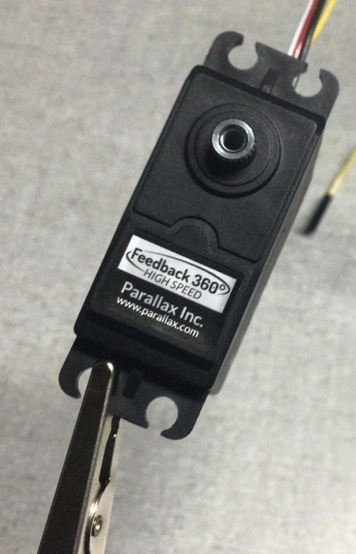
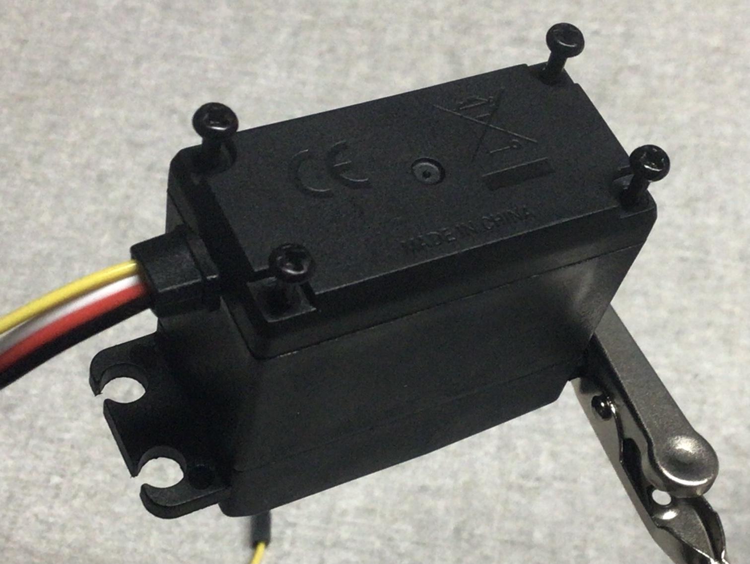
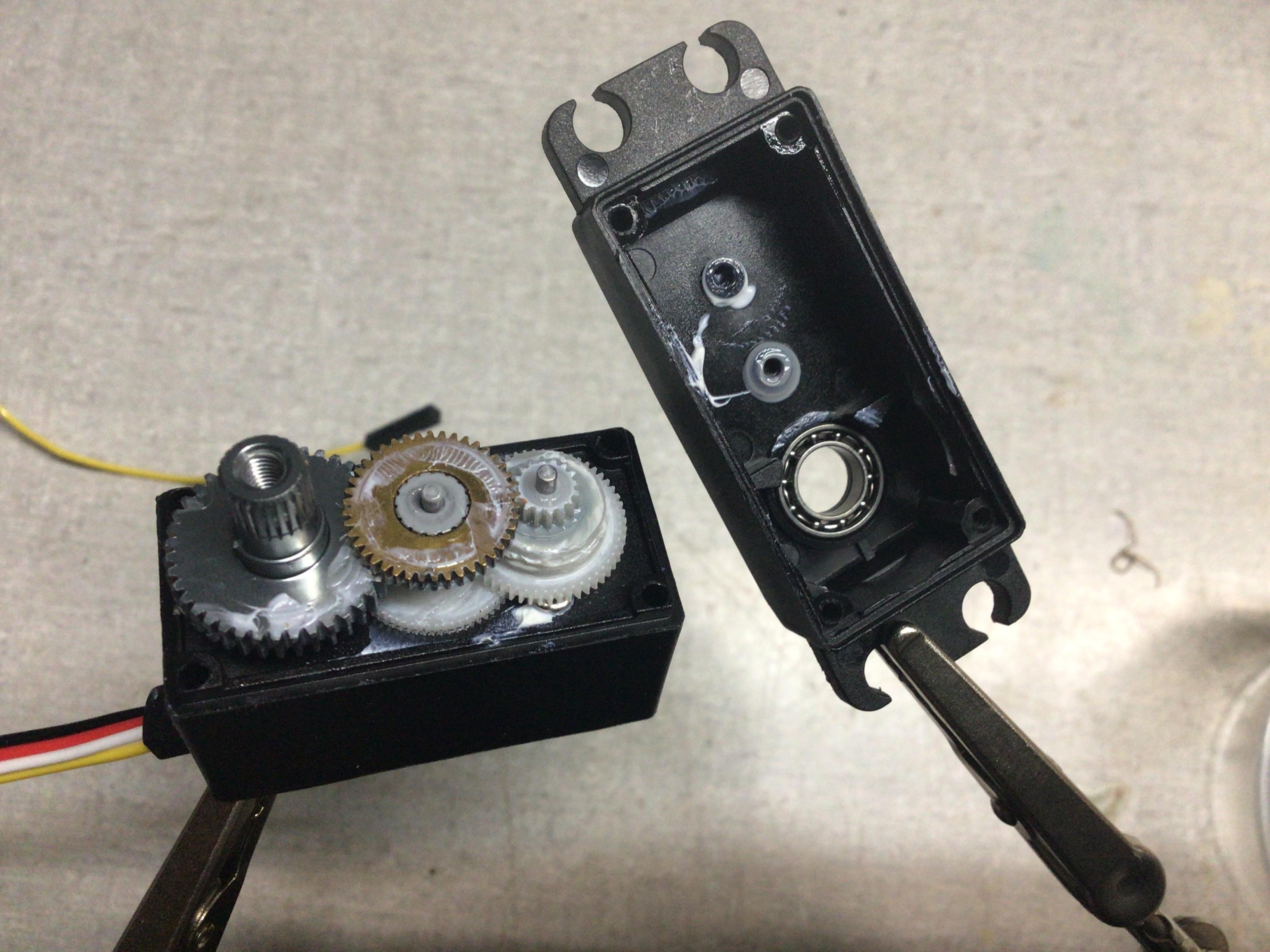
The Feedback 360 is housed an a pretty standard servo casing. The only difference is that it has an extra fourth wire, separate from the standard 3-wire servo plug, that carries the feedback signal from the encoder. It comes apart with the usual four screws at the bottom. Pretty notmal for a servo.
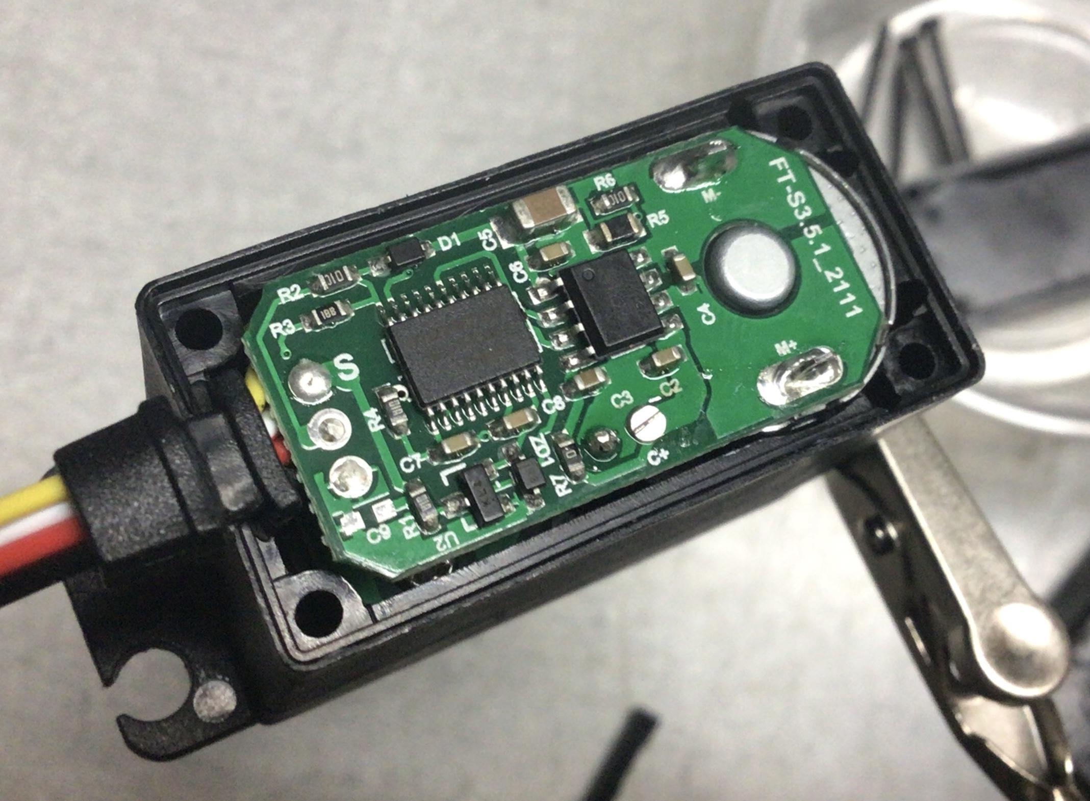
I was surprised to find the inner controller board was much more complicated than any standard servo I had looked inside of. Usually there is just one or two ICs, each with only a few (8-10) pins, a couple of resistors and capacitors, and the motor. The Feedback 360 had many tiny resistors scattered all over, and one large chip with a whopping 20 pins!
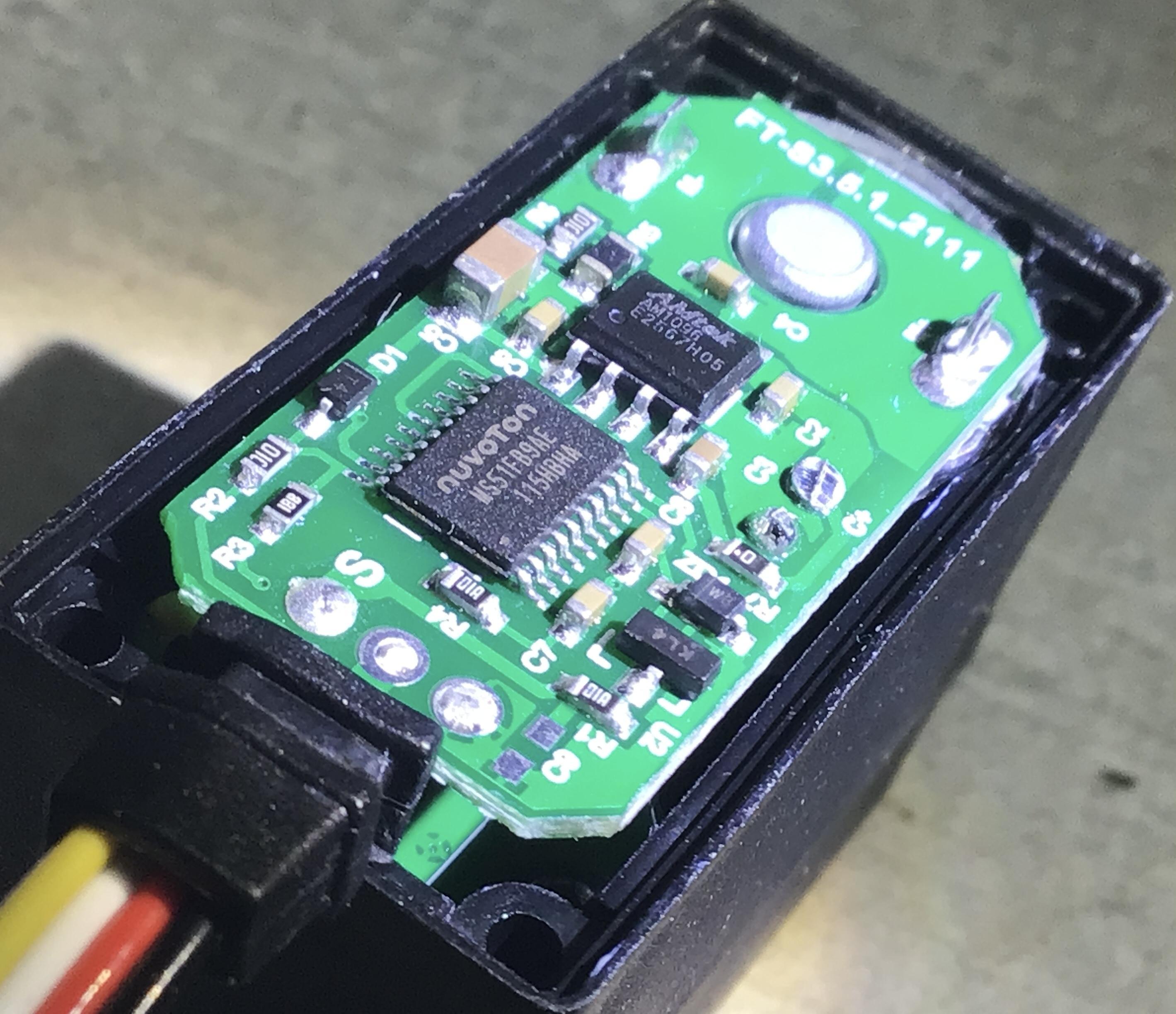
Getting a closer look at it with a light revealed what the two chips were: the one with 8 large pins is an AMTek AM1096, which is a combination single H-bridge and 3.3V linear regulator.
The one with more pins – and this is what really surprised me – is a Nuvoton MS51, a powerful microcontroller with 18 GPIO pins, 6 PWM timers, an SPI/I2C/UART buffer, 8 ADC channels, the list goes on and on. This chip seems a bit overkill for something as simple as decoding a servo pulse and driving an H-bridge. You only need 3 GPIO pins and like 15 lines of well-written C code to do that. Here it is as an arduino sketch, for the ATtiny85:
//             Signal pin = 3     Forward pin = 0     Backwards pin = 1
void setup() { pinMode(3, INPUT); pinMode(1, OUTPUT); pinMode(0, OUTPUT); }
void loop() {
    int width = pulseIn(3, HIGH);
    if (abs(width - 1500) < 20) { digitalWrite(1, LOW); digitalWrite(0, LOW); } // Deadband
    else if (width < 1500) { digitalWrite(1, LOW); analogWrite(0, map(width, 1500, 1000, 0, 255)); } // Forward
    else { analogWrite(1, map(width, 1500, 2000, 0, 255)); digitalWrite(0, LOW); } // Backward
}
The MS51 may also be the source of the delay I found when trying to control the position; Parallax could have programmed in a low-pass filter to “smooth” the signal to the motor, and a typo somewhere in their code may have caused the smoothing to be too great (e.g. cutoff frequency of 1Hz instead of 10 or 100Hz).
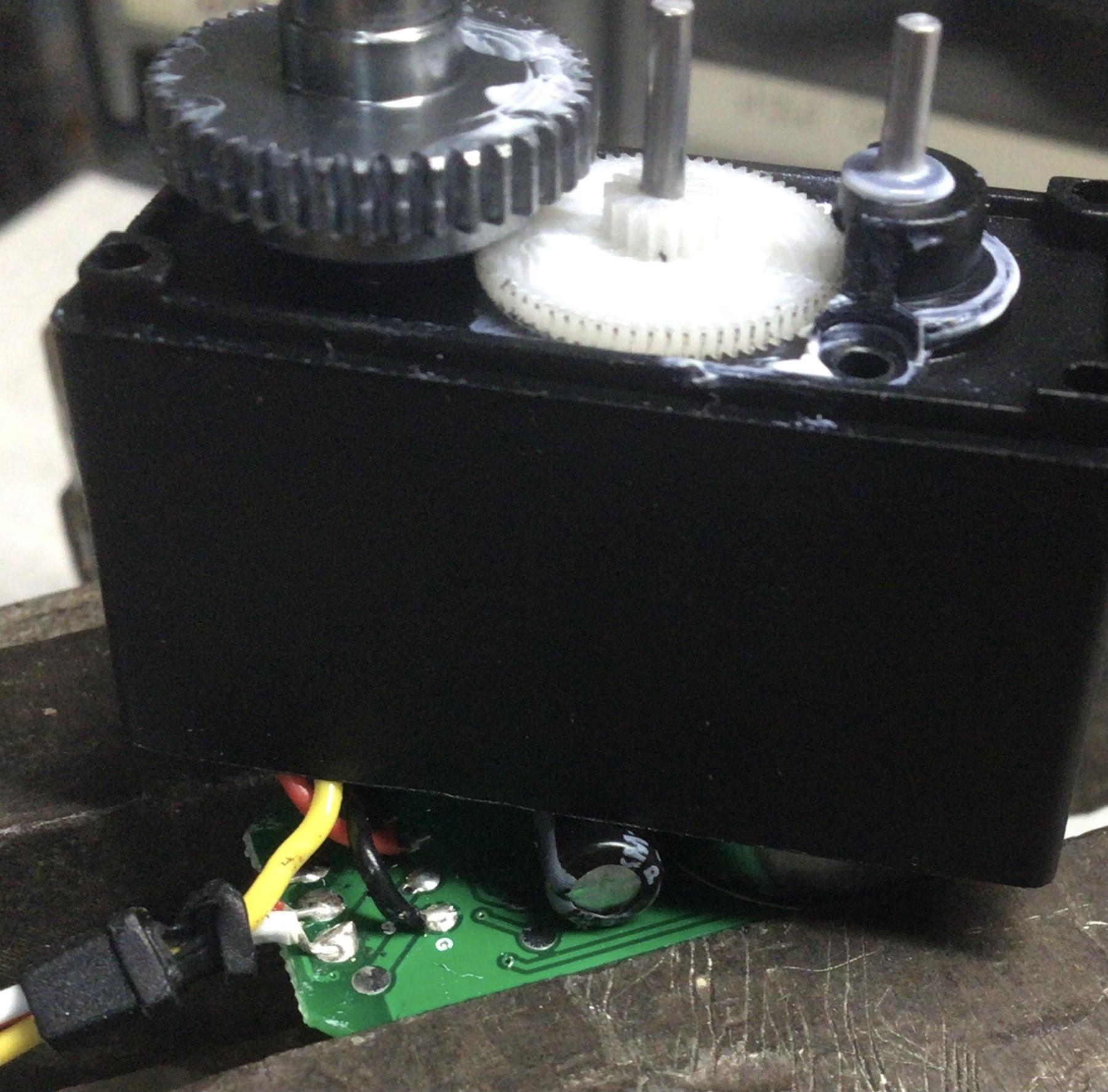
The top of the servo just has some pretty standard servo gears, all covered in white grease. The output shaft has two ball bearings. I might steal them and use them in another project somewhere else later on.
Removing a few gears and then the motor bolts failed to allow the motor to slide out – it was friction-fit as well as bolted. I had to push on the top gear with a screwdriver, clamp the board in a vise, and twist and pull to get the motor to budge.
The inside board (which contains the sensor) was connected to the main board by just 2 wires, with the yellow signal wire that outputs the signal not passing through the main board at all, indicating the signal was generated by the chip on the board.
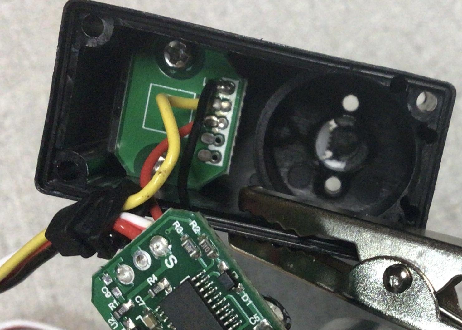
After unscrewing that board, the sensor chip is revealed: an AMS AS5600:
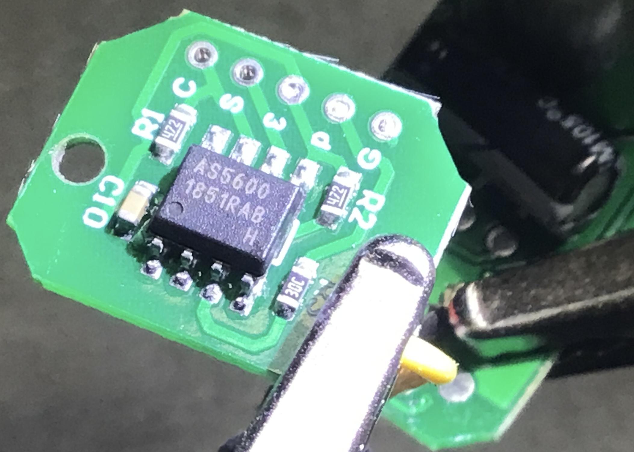
And if I read the datasheet correctly, the I2C pins are broken out on separate holes on the little board – so maybe I can get in and re-program my sensor!
It surprised me how simple this motor is. And it also prompted me to ask: why does it cost so much? The Feedback 360 servo costs close to $30, whereas a standard Parallax servo costs more like $10. DigiKey sells bare AS5600s for only $3.50, so that can’t be the source of the price increase.
I’m guessing it’s all in the configuration: the labor cost that the Parallax engineers had to work on to be able to come up with such a product. And good for them, because I would never have thought of it myself.
Related Posts