Images
This page contains the images I took of the two Armdroid units.
The other accessories each have their own page:
Base and Shoulder
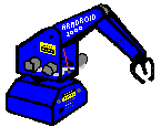
Here’s all the power connectors on the base:
The fourth accessory output is mounted on the shoulder.
The labeling on the Armdroid 1000 was a little bit confusing. The serial number label on the base lists the address of D&M as “PO Box 2102, Fargo, North Dakota, 58107”, but the stickers on the stepper motors simply list it as “Moorhead, Minnesota”.
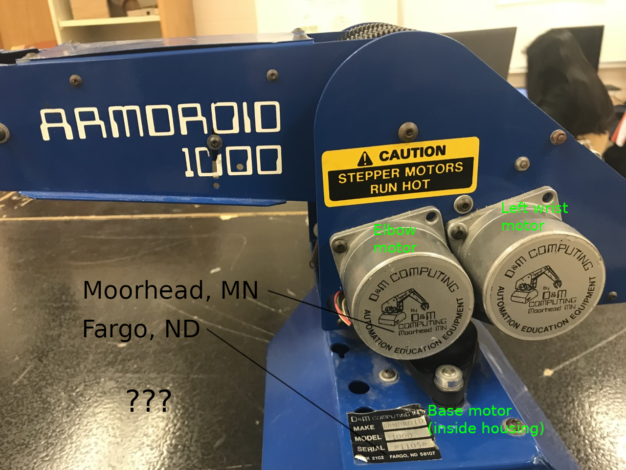
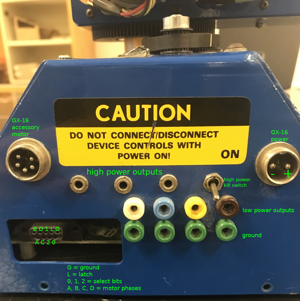
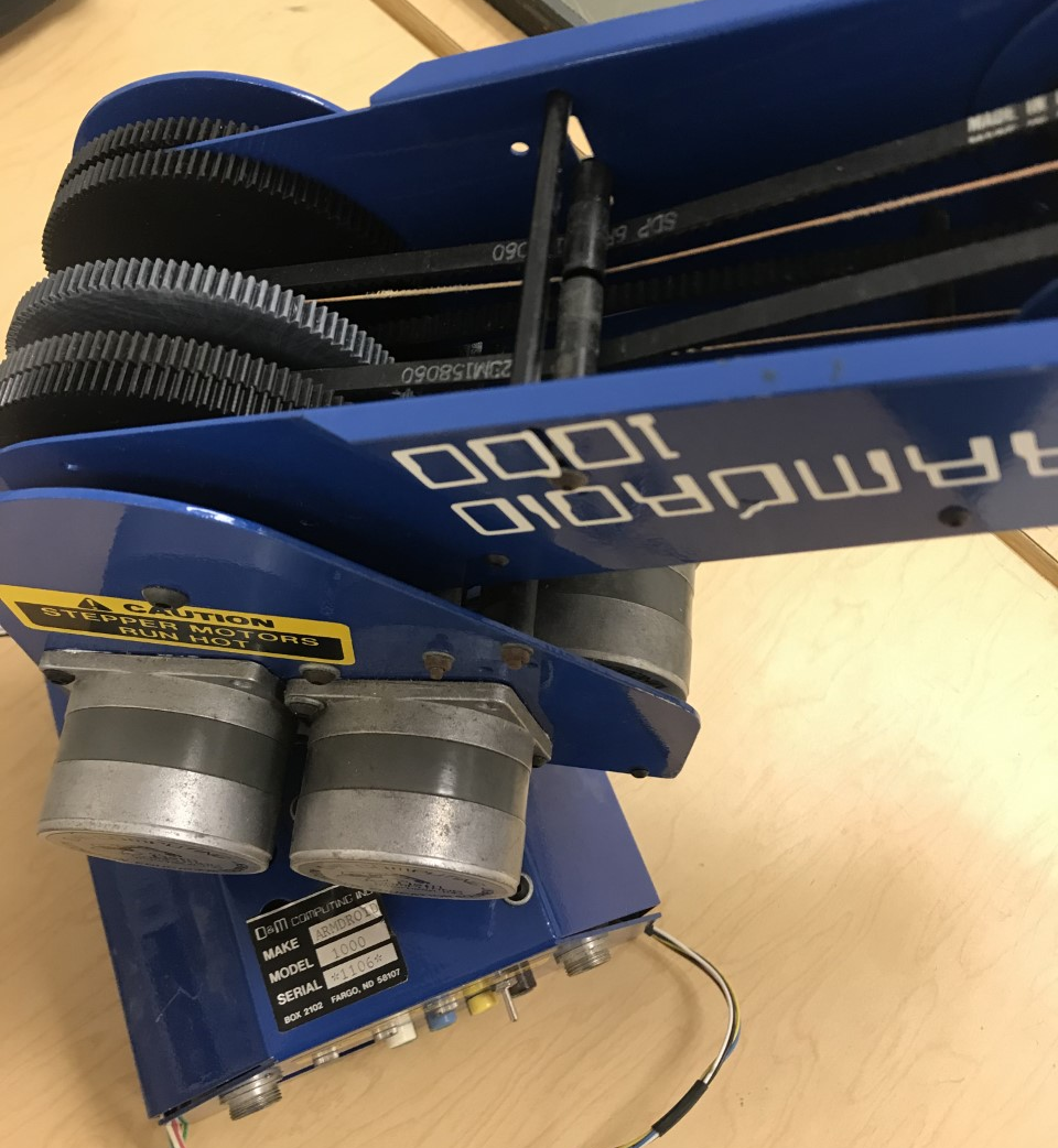
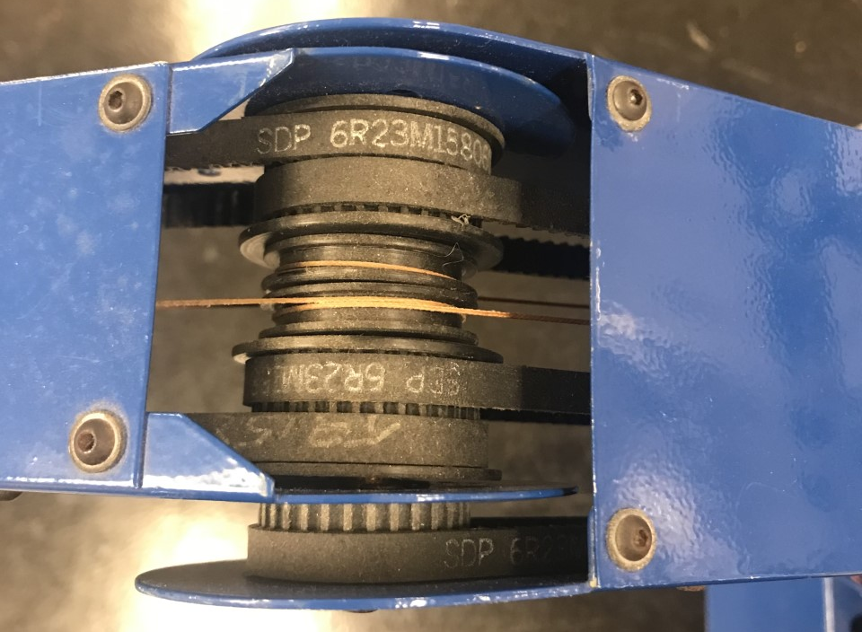
The shoulder contains five of the six stepper motors that drive the movements of the Armdroid 1000. The motion is transmitted up to the joints by toothed timing belts and pulleys.
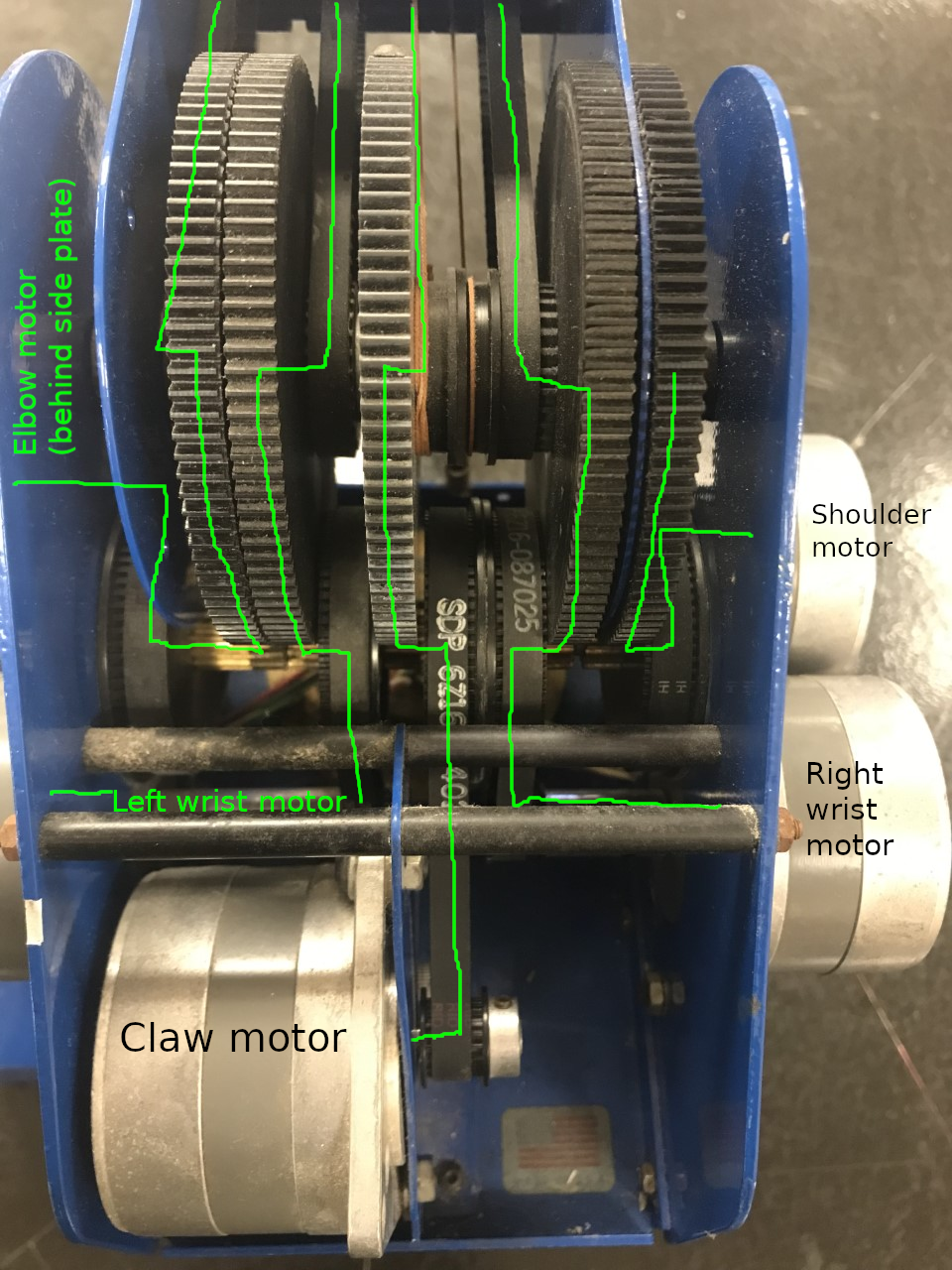
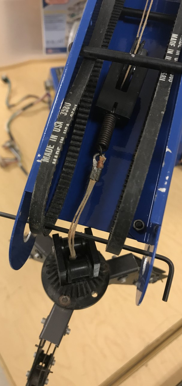
Most of the joints have a pretty wide range of motion. The shoulder joint can easily flip over backwards and reveal the belts and tension rollers underneath.
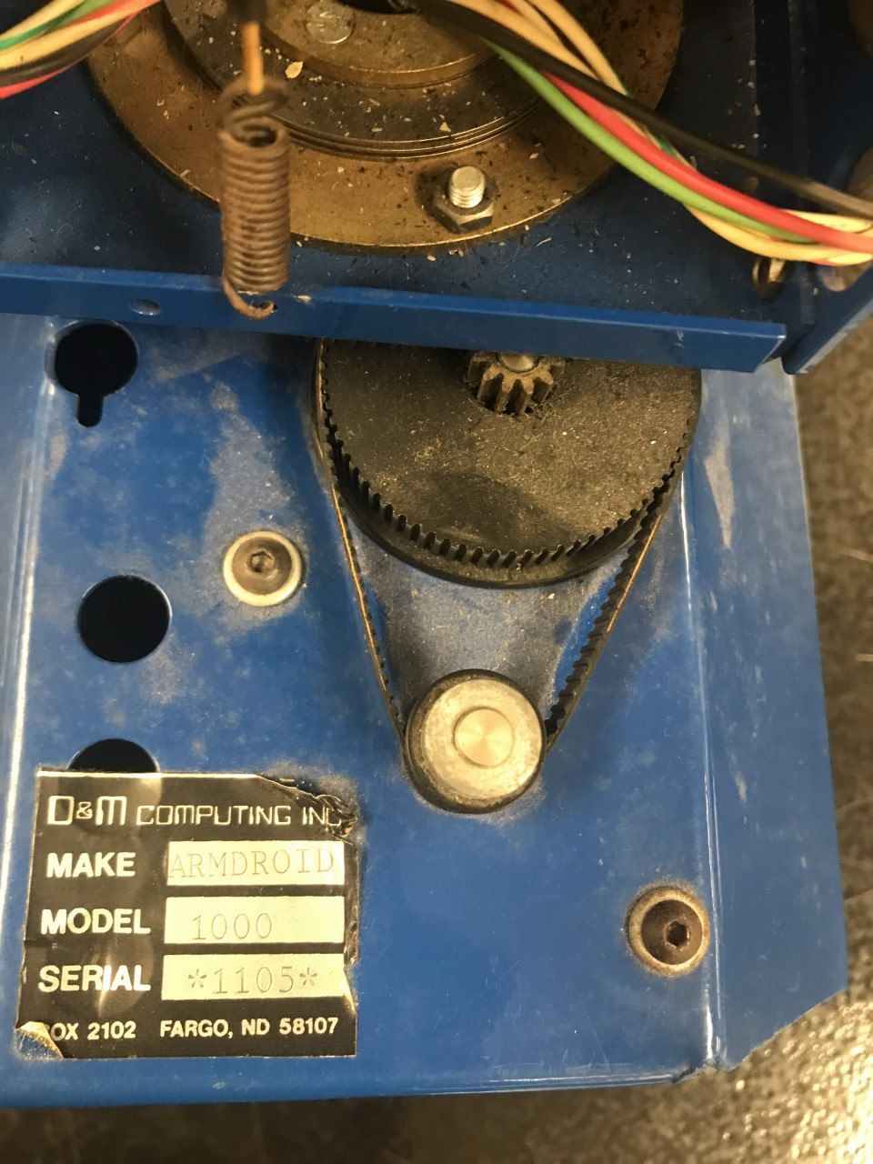
The sixth motor rotates the base bearing via another gear-and pulley setup.
Elbow and Claw
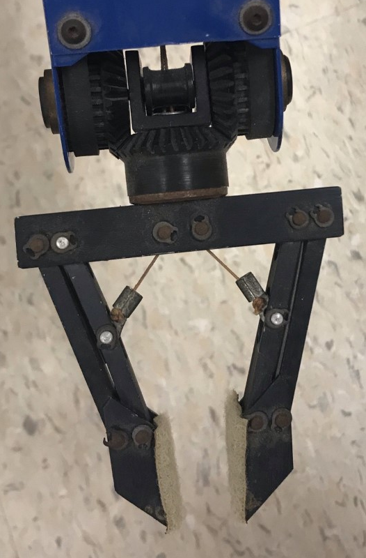
The elbow simply transmits the motion of the wrist belts and claw string. The pulley on the side is fixed to the forearm and is turned by the elbow motor belt.
The intact Armdroid (serial number 1105) had the two-finger claw on it. The broken one (serial 1106) had the cool three-finger claw that all the Armdroid 1’s have, but unfortunately, it was broken.
Circuitry
The circuit board inside contains a bunch of microchips in sockets (most from the 74LS series) that form a giant demultiplexer that routes the control signals to the right motor or output.
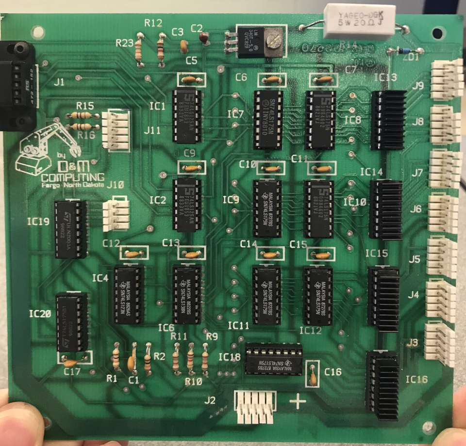
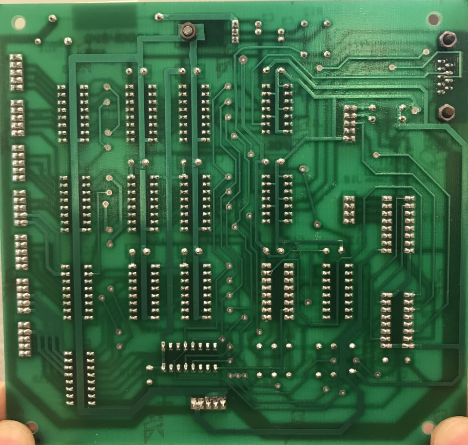
Dan Kohn has done the work of figuring out the general schematic of the circuit inside (although his pinout of the DB9 connector differs from the one I found above). You can find his schematic here (and if that goes down, there’s a link to a local copy here). His part numbers differ slightly, but they’re just different companies’ takes of the same functional component.
On my board, the inputs from the DB9 connector are first amplified by 74LS125 buffers so they can drive the large number of inputs. From the buffer, the select bits go to a 74LS138 3-to-8 converter. The latch bit goes to a 74LS123 monostable multivibrator that normalizes the pulse length and sends it to an enable input of the 74LS138, routing a clock pulse to the appropriate one of the eight 74LS175 D-latches to latch in the phase bits for that motor. The ULN2003As switch the high current needed for the motors.
There is more point-to-point wiring inside the base (here of the broken Armdroid, 1106). The motors all come down and terminate in a plug (including the accessory motor port wires), and there is a large reverse-polarity protection diode on the power connector. The positive wires also go through a kill switch and to one terminal of each of the accessory outputs. The low power outputs are wired to their own plug.
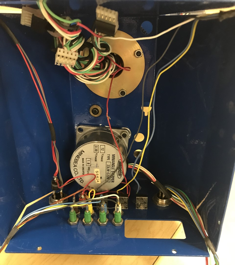
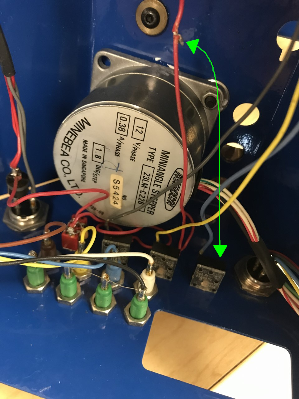
Taking a closer look, the motor is a standard 200 steps/revolution unipolar motor. Unfortunately, in the broken Armdroid, the shoulder had been twisted around so many times that the wire leading up to the fourth accessory output in the shoulder broke the terminal of the third output and tore some of the wires leading to the motors.