
Circuit Work, part 1
This post is part 1 of the circuit-work series:
Today I started to work out the circuit of the small control board in the conveyor belt, before I tackled the larger circuit board in the Armdroid itself. There are pictures of this circuit board on the conveyor images page.
First, I worked out the power supply. This is the entire top half of the board, and the traces are very wide, as the motor is very power-hungry:
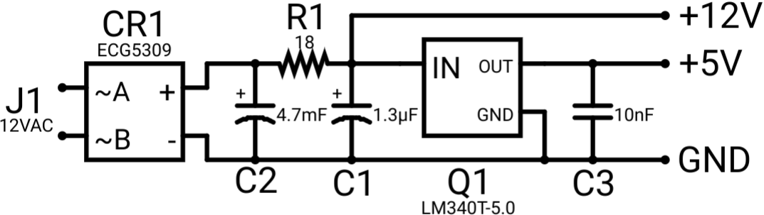
This is just a standard LM7805-or-equivalent DC power supply circuit. The 12 volts AC is rectified and fed into the buffer capacitor, and it is then regulated down by a low-value resistor and a linear regulator to 5 volts for the logic circuits.
Next is the 555 timer clock circuit:
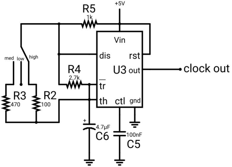
Again, this is a very standard circuit to generate a clock signal using a 555 timer. The chosen values for the resistors cause the circuit to oscillate at 47 Hz for low speed (only R4 connected), 168 Hz for medium speed (R3 & R4 in parallel) and 252 Hz for high (R2 & R4 in parallel), according to the Falstad simulator. (It uses a lot fo power in my opinion. If R2, R3, R4, and R5 were swapped out for 1kΩ, 4.7kΩ, 27kΩ, and 10kΩ, and C6 changed to 0.47µF, it would still oscillate at the same frequencies while using only 10% of the power as the existing circuit.)
I have not been able to work out the circuit of the latches and motor driver yet. It’s hard because some of the traces are hidden under the IC sockets. Hopefully I will figure it out soon.