3 pins? Yes
It’s been quite a while since I last shared an update. But then again, not much has happened since then, either.
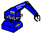
I figured out how to remove the claw from its mounting on the wrist joint, and replaced it with the old-style three finger gripper from the spare-parts Armdroid. And, as I had read elsewhere, it looked very creepy and lifelike when I operated it – that is, until one of the three strings connected to the fingers snapped (it had probably dry-rotted) and rendered the whole claw useless and I was forced to reinstall the standard 2-finger gripper.
I also was able to install the new Anderson-connector power adapter I had made up earlier, and although I had to hot-glue it in (the hole was slightly too small for me to wedge it in by friction), it was a clean swap and now I can run the armdroid nicely off the 12-volt batteries. I also soldered a long wire onto the Armdroid’s internal 5V line and connected it using an old Fischertechnik plug pair to a spare 10th wire on my patch cable (I had thought of this in advance!) so the Arduino could be powered off the Armdroid’s 5V supply.
The Arduino program I initially wrote still worked, and it worked very well for what it did. Unfortunately I have not yet been able to add any sort of autonomous movement, but I don’t think that would be too difficult. The only downside is that trigonometry on the Arduino is very slow – although it can can be sped up a lot from the default.
The original interface to the Armdroid I made used a parallel port, which occupied 8 pins of the Arduino and I really couldn’t do much else (sensors, etc). I also didn’t have any serial-in parallel-out pin expander chips to be able to reduce the pin usage of the Arduino.
Then my engineering teacher taught us about shift registers and how they are made out of flip-flops… and I remembered that I had a spare Armdroid circuit board lying around, which conspicuously uses eight quad D flip flop integrated circuits (74LS175) to hold the bits for the stepper motors. Since I didn’t need the circuit board, I pulled out two of them (thank God for the IC sockets!) and started wiring them up into a shift register. I also wrote some Arduino code to interface it to the homebrew shift register. I haven’t completely wired it up yet, but I’m crossing my fingers it will work. In theory it should.
